...

FT14 FTGS14 Series Float Steam Traps

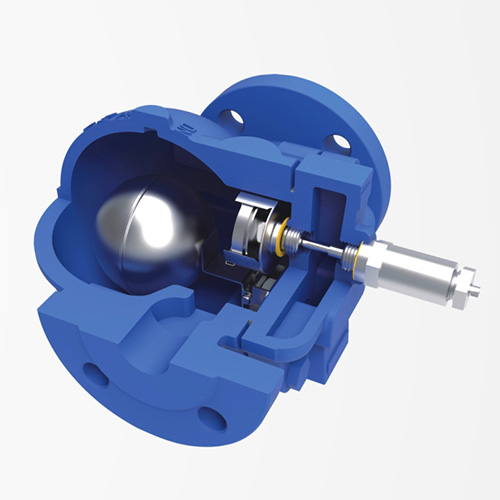
The installation direction is adjustable, the maximum pressure difference is 14bar, and the maximum displacement is 1260Kg/h


Features

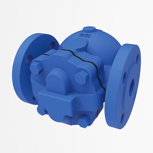
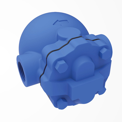
Variable installation methods:

The flow direction can be changed on site by simply rotating the valve cover according to the pipeline flow direction requirements (make sure the arrow on the nameplate points downward)

Get A Quote
Product Description
Materials Selection Restrictions Installation Instructions
• FT14 body, bonnet: GGG40
• FTS14 body, bonnet: Austenitic stainless steel
• FTGS14 body: Austenitic stainless steel
• Bonnet: GGG40
• Seat: Martensitic stainless steel
• Disc: Martensitic stainless steel
• Other internal parts: Stainless steel
•Built-in filter, with the letter “X” after the model number
•Steam breaker and steam lock device, with the letter “C” after the model number Note: The steam breaker and steam lock device is used to prevent the occurrence of basic steam lock in the system. The valve that is equipped with the steam breaker and steam lock device still has an air exhaust device.
• Design pressure (PMA): 16bar
• Maximum operating pressure (PMO): 14.6bar
• Maximum operating temperature (TMO): 250°C
Note: When installing, make sure the fluid flow direction is consistent with the direction indicated by the arrow on the valve body, and ensure that the float arm is horizontal so that the float can rise and fall freely and vertically.


Dimensions/Weight (approximate) mm and Kg

model FT14(FTS14) FTGS14
Connection Type Thread Flange Thread Flange
Nominal diameter 15 20 25 15 20 25 15 20 25 15 20 25
A(mm) 121 145 150 160 121 145 150 160
B(mm) 107 117 107 117 107 117 107 117
C(mm) 67 75 101 70 80 70 114 83
D(mm) 147 166 162 170 160 162 175 183
E(mm) 40
Weight(Kg) Thread 3 3 4 / 3.4 4.5 /
Flange / 4.5 5 6.5 / 4.9 5 7


Technical Parameters

model FT14 FTS14 FTGS14
Connection Type Threaded, integral flange
Installation method (flow direction)
Model rear belt (RL) horizontal connection from right to left←
Model rear belt (LR) horizontal connection from left to right →
Model rear band (V) Flow direction downward vertical connection↓
Maximum working pressure difference (PMX) (A) 4.5 bar
(B) 10bar
(C) 14bar


Additional cold water discharge capacity of the thermostatic air exhaust valve under start-up conditions

The displacement in the figure is based on the condensate displacement at saturation temperature. During the startup phase, the condensate is cold and the thermostatic air exhaust valve is open to provide additional condensate displacement. The table provides the additional cold water displacement of the air exhaust valve under different pressure differences:


△P(bar) 0.5 1 2 3 4.5 7 10 14
Minimum additional cold water discharge capacity (Kg)
1/2″ and 3/4″ 70 140 250 380 560 870 1130 1500
1″ 120 240 360 500 640 920 1200 1500
RELATED PRODUCTS
Get a cost-effective lock and
tag solution today!
icon
icon