...

BT Series Clean Pressure Balanced Steam Traps

Vertical installation, maximum pressure difference 7bar, maximum displacement: (cold water 1900Kg/h), (hot water 1350Kg/h)


Introduction

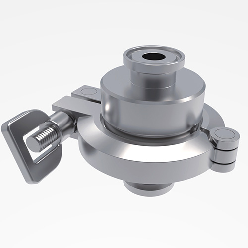
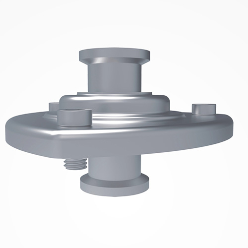
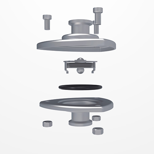
BT series clean steam traps are designed for draining clean and pure systems. They can be used in sterilizers, main drains, CIP/SIP systems and process vessels. The valve body is made of 316L stainless steel with a high internal surface finish and a 150° tilted seat to ensure self-drainage.


Get A Quote
Product Description
Features Materials Restrictions
Rapid air discharge ensures quick start-up and continuous operation.
Seamless design inhibits bacterial accumulation to the greatest extent.
The valve seat is designed to be inclined 150 degrees to ensure self-drainage.
The inner surface polishing degree can reach Ra0.8um.
• Valve body, valve cover: F316L
• Valve seat: F316 • Liquid capsule: 316
• Clamp: 316L
• Sealing ring: sanitary grade fluororubber
Design pressure (PMA):
• SM45: 110 bar
• SM65: 160 bar
Maximum operating pressure (PMO) @ maximum operating temperature (TMO)
• SM45 type: 45bar @ 450°C
• SM65 type: 65bar @ 475°C


How it works
The working element of the BT series is a stainless steel bladder (thermostatic element). When the machine is cold or started, the bladder (temperature sensing element) is in a relaxed state, and the valve core and valve seat are fully open to discharge a large amount of air and condensed water. When the system temperature approaches the saturated steam temperature, the liquid in the bladder expands (the thermostatic element is deformed by heat), pushing the valve core to the valve seat to close and prevent steam leakage. The closing temperature is close to the saturated steam temperature, ensuring effective drainage of the system.

Technical Parameters

model BT6 BT7
Maximum allowable pressure 10bar
Connection Type Clamp Thread, welding, clamp
Installation
Vertical↓
Maximum working pressure difference (PMX) (A) 6 bar 7bar


Dimensions/Weight (approximate) mm and Kg

model BT6 BT7
Nominal diameter 15 20 25 40 8 15 20 25
A(mm) 65 58 75 82 95
A1(mm) / / 50 55
A2(mm) / 105
B(mm) 64 70
C(mm) 73 /
D(mm) 75 /
Weight(Kg) Clamp 0.7 0.8 0.9 1 0.6 0.7 0.9


Installation Tips

The BT system is designed to be installed vertically with the flow direction downward to ensure self-drainage of the valve body. Please check the flow direction arrow on the valve body during installation. A cooling pipe must be left upstream to prevent condensate from accumulating on the process equipment during normal operation. The temperature sensing element cannot be placed in an overheated condition.

RELATED PRODUCTS
Get a cost-effective lock and
tag solution today!
icon
icon