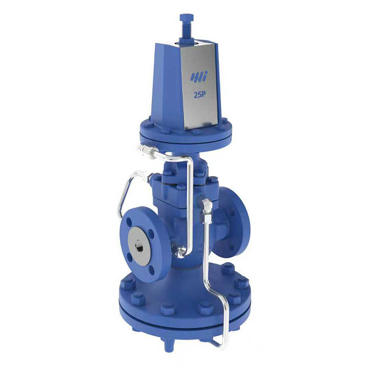
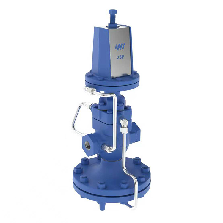
25P Self Acting Pilot Valve Type Pressure Reducing Valve
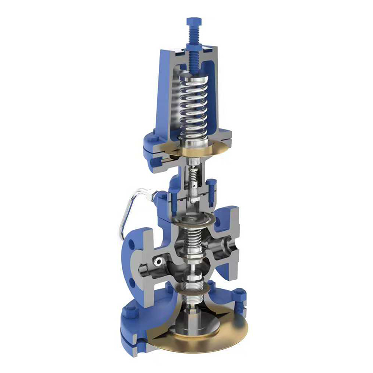
The 25P is a self-acting pilot-operated pressure reducing valve. It senses downstream pressure through an external pressure sensing tube, adjusts the main valve opening, and maintains stable pressure. The valve can be closed when there is no downstream load.
Get A Quote
Share:
Product Description
Constraints (Ductile)
● Design pressure (PMA): 21 bar ● Maximum operating pressure (PMO): 17.2 bar ● Maximum operating temperature (TMO): 232°C
Downstream pressure range
Three different colored springs are available to control downstream pressure: ● Yellow: 0.2 bar – 2.1 bar ● Blue: 1.4 bar – 7.0 bar ● Red: 5.6 bar – 14.0 bar
Bill of Materials
● Valve body and cover: QT400-18 ● Main valve seat and pilot valve seat: Martensitic stainless steel ● Main valve disc and pilot valve core: Martensitic stainless steel ● Pressure regulating spring: Silicon-chromium spring steel ● Other internal parts: Stainless steel
Flow
The table below shows the Cv value when the valve is fully open, which is used for safety valve selection.
Cv value
caliber
1/2″
3/4″
1″
11/4″
1/2″
2″
21/2″
3″
4″
5″
Cv
3.48
6.5
10.5
14
20
35
56
74
115
123
Conversion formula: Cv(US) = Kv x 1.156
Dimensions/weight (approximately) mm and kg
model
25P
Nominal diameter
15
20
25
32
40
50
65
80
100
125
A(mm)
140
152
184
216
/
A1(mm)
160
166
205
216
240
288
316
361
400
B(mm)
193
219
269
346
397
C(mm)
309
322
338
297
294
325
D(mm)
157
171
179
208
354
367
410
E(mm)
466
479
501
546
651
661
735
Weight (Kg)
Thread
11
10.5
14
16.5
16
26
/
flange
12
12.5
16
19
20.5
31.5
63
75
112
132
25P pressure reducing valve steam flow diagram
Note: This diagram is for reference only. For critical applications, it is recommended to select the appropriate flow meter based on CV (CV) calculations. The suggested CV value for actual operating conditions should be between 20% and 80% of the valve’s total CV. This flow meter is based on the installation of an external sensing tube. Without an external sensing tube, the flow rate will decrease. Under very low downstream pressure conditions, the flow rate reduction can reach up to 30%.
How to use flow charts The following two examples of saturated steam and superheated steam will explain how to use this flow chart.
Saturated steam flow rate 5000 kg/h, pressure reduced from 8 bar to 5 bar. Finding the valve diameter that meets the flow requirements by moving vertically downwards from the fulcrum of the upstream pressure of 8 bar and the downstream pressure of 5 bar, an 80 mm valve is found to be the minimum acceptable diameter. Due to the higher specific volume of superheated steam, the data obtained from the diagram needs to be corrected. The correction factor for superheating at 55°C (100°F) is 0.95, and the correction factor for superheating at 110°C (200°F) is 0.9. Therefore, with an 80 mm valve, if the steam is superheated to 55°C, the flow rate is 5900 × 0.95 = 5600 kg/h, which is still sufficient to meet the required 5000 kg/h.
Decomposition methods, troubleshooting, and solutions
● Most pressure reducing valve malfunctions are caused by foreign objects and impurities in the pipeline; please pay special attention. ● Malfunctions of pressure gauges, leaks or gaps in bypass valves, and clogged filters are very similar to valve malfunctions; please confirm the above items before taking any corresponding actions.
Inspect and replace the pilot valve core and valve seat.
1. Unscrew the four bolts securing the pilot valve base cover. Remove the pilot valve and inspect the pilot valve spool and seat. 2. The pilot valve spool and seat are a single, complete assembly. 3. Use an 11/16″ hex wrench to remove the pilot valve spool and seat assembly. 4. If wear is found on the spool or seat, replace the entire assembly.
Inspect and replace the pilot valve diaphragm
1. Rotate the adjusting screw counterclockwise until the spring relaxes. 2. After loosening the bolts, remove the pilot valve bracket cover. 3. Inspect the two pilot valve diaphragms for twisting or breakage. 4. Clean impurities and dirt from the bottom of the pilot valve diaphragm chamber. 5. When replacing the pilot valve diaphragms, clean the casting surface to ensure a seal. 6. Install the pilot valve bracket cover, paying attention to its center position. 7. Tighten all bolts.
Inspect and replace the main valve core and main valve seat.
1. Disconnect all connecting pipes. 2. Loosen the valve cover bolts. 3. Remove the main valve cover, filter screen, spring support, and main valve spring. 4. Use pliers or a similar tool to remove the main valve core. 5. Check for dirt or other impurities that may obstruct the tight closure of the main valve core and main valve seat. 6. If the main valve core and main valve seat show signs of wear, but are not severe, they can be polished with fine polishing compound (400 grit). Check for valve erosion. 7. If the main valve seat must be replaced, it can be removed from the valve body using a standard hex socket wrench. When replacing the main valve seat, a new washer should be used to ensure a tight closure.
Inspect and replace the main valve diaphragm.
1. Loosen the connecting pipe . 2. Remove the bolts connecting the main valve diaphragm disc to the base. 3. The diaphragm disc base can now be removed. 4. Inspect the two metal “main valve diaphragms” to determine if they are twisted or damaged due to improper operation. 5. Simultaneously, remove any impurities from the diaphragm chamber. 6. Check that the valve stem can move freely and ensure the guide bearing is free of blockages. 7. Before reinstalling the main valve diaphragm, the main valve core and main valve seat should be in the closed position. 8. Ensure the tray is accurately positioned. 9. Ensure the diaphragm is centered and tighten the bolts.
Fault Diagnosis
Fault
reason
Overhaul
1. Under normal load, the control pressure exceeds the set value.
There is dirt or impurities between the pilot valve core and the valve seat.
Loosen the adjusting bolt, remove the guide pipe (upper connector), and introduce steam. If steam flows out from this interface, the pilot valve core and seat assembly needs to be removed for cleaning or replacement.
There are impurities between the main valve core and the valve seat.
Inspect and clean the valve core and valve seat.
Control hole or sensor blockage
Remove the tubing, inspect the control port, and clean it.
2. Control pressure exceeds the set value only at low loads.
The main valve core and seat are worn or contain impurities.
Inspect and clean the valve core and valve seat.
The valve was selected too large.
Under low load, the adjusting bolt reaches the required pressure.
Bypass valve not closed tightly or leaking
Inspect, and repair if necessary.
Impurities in the main valve stem and guide bearing
Disassemble, inspect and clean
3. The pressure reducing valve cannot be opened.
Main valve diaphragm rupture
Close the bypass valve and disconnect the diaphragm disc base connector. If steam flows out of the diaphragm chamber, the diaphragm is damaged and needs to be replaced.
Control hole blockage
Remove conduit A and clean the diaphragm disc base connector.
The pilot valve seat is blocked by impurities.
Remove the valve core and seat assembly, inspect and clean it.
The filter is clogged.
Check and clean
clogged pipe filter
Check and clean
Improper adjustment of the pilot valve adjusting bolt
Adjust to the set pressure
4. Control pressure is too low
Improper adjustment of the pilot valve adjusting bolt
Adjust to the set pressure
The pressure reducing valve is too small.
Verify the actual flow rate against the valve’s rated flow rate.
The supply steam pressure is too low
Check and correct
Main valve diaphragm rupture
Close the bypass valve and disconnect the diaphragm disc base connector. If steam flows out of the diaphragm chamber, it indicates that the diaphragm is damaged and needs to be replaced.
5. The pressure reducing valve cannot be closed.
Drain hole connector missing
Replace with a suitable connector
The sensor tube is blocked or not installed.
Disassemble, inspect, and clean, or install.
A rupture in the diaphragm of the pilot valve (water or steam flows out from the pilot valve spring guide seat).
Replace pilot valve diaphragm assembly
Defective pilot valve assembly or main valve seat threads
Check valve seat erosion condition
Main valve diaphragm rupture
Loosen the bolts, replace the diaphragm, and then tighten them again.